Clipping Planes

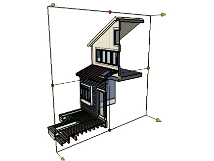
Clipping plane parallel to XY and positioned in
the middle of the visible objects.

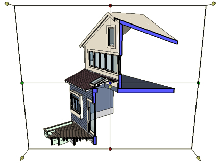
Clipping plane perpendicular to the line of sight.

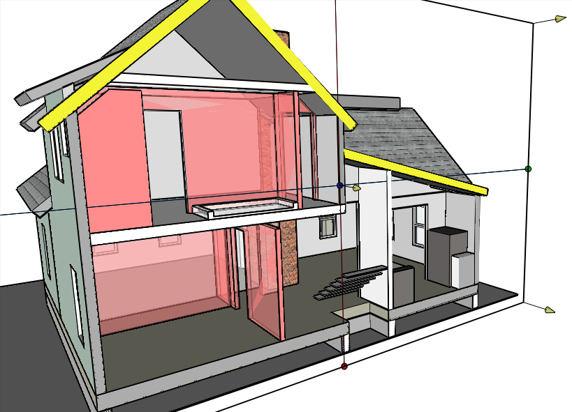
Cross sections painted differently.

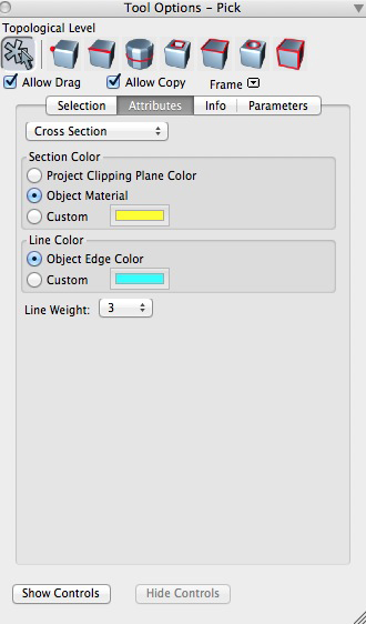
Cross Section options in Attributes tab of
Pick Tool Options palette
Clipping planes are a useful way to see the inside of a model by cutting away part of the model to reveal the interior and the structure of its mass. The Section tool, discussed later, can be used to accomplish this, however, it actually cuts the model. While this might be desirable in some cases it is often desirable to have a way to visualize sections of the model without affecting the model itself. A clipping plane is used for just such visualization. A clipping plane cuts the scene at a desired location. Multiple clipping planes can be maintained in the Clipping Planes palette making it easy to switch to different cut-away views with a single click. To create a clipping plane, first open the Clipping Plane palette (located at the bottom of the palette dock). Click on the New (![]() ) icon at the top of the palette. A new clipping plane is added to the palette and it becomes the active clipping plane. The plane is positioned by default in the middle of the visible objects and oriented parallel to the XY, YZ, or XZ plane depending on which plane best faces the current viewing position.
) icon at the top of the palette. A new clipping plane is added to the palette and it becomes the active clipping plane. The plane is positioned by default in the middle of the visible objects and oriented parallel to the XY, YZ, or XZ plane depending on which plane best faces the current viewing position.
You can also create a clipping plane that is positioned relative to the current view. That is, a plane that is perpendicular to the current line of sight. To do so, select the New Clipping Plane From View item from the context menu, accessed from the icon (![]() ) in the upper right of the Clipping Planes palette.
) in the upper right of the Clipping Planes palette.
When a new clipping plane is created, it is made active and the plane is shown graphically on the screen. The graphics include a number of on screen controls that are used to graphically edit the position and orientation of the plane. There are 5 arrow controls that point in the direction of the cutaway mass and can be used to reposition the clipping plane along its primary axis (perpendicular to the plane). The blue dot at the center of the plane can also be used to move the plane along the axis; however, it works a differently than the arrows. When using the blue dot, the model is not sectioned live as the clipping plane is moved. This allows for the plane to be positioned accurately by snapping to parts of the model. Note that you may first need to move the clipping plane once to reveal the part of the model you desire to snap to and then move it to its final position.
The green and red dots can be used to rotate the clipping plane. Note that, when the plane is rotated, the graphics are updated so they are big enough to enclose the entire visible model (if the clipping plane was positioned at the widest portion relative its axis).
|
The clipped cross sections can be painted with different colors. This is done through the cross section attribute that is assigned to all objects. You can access the parameters of this attribute through the Pick Tool Options palette. With the Pick tool select the object to invoke its tool options palette, then select Attributes, and, from the popup menu on the top, select Cross Section. The options displayed contain parameters for the Section Color, the Line Color and Weight. Any change you make to any of these parameters will be reflected to the display of the cross section on the screen. |
New in v. 3.0 |
Right clicking on any of the editable controls invokes a context menu with three items. When the 2D option is selected, only the 2D intersection with the clipping plane is shown. The Flip item reverses the direction of the active clipping plane. That is, it toggles which side of the model is visible and which is cut away. The Make Permanent (Cut Section) item actually cuts the model at the clipping plane. This is equivalent to using the Section tool on the visible objects along the clipping plane.
When a clipping plane is active the plane affects the entire working environment. You cannot pick objects or parts of objects that are not visible. Likewise snapping does not work on the portions that are cut away. The clipping plane does not affect guides and other on screen graphics and controls. The faces of solid objects created by the clipping plane are shown with a dark gray color by default. The color can be changed in the Appearance tab of the Project Settings dialog, by using a custom style.
The Clipping Plane palette is used to manage the clipping planes. The first column of the palette shows whether the plane is active, which is indicated by a red dot ( ). Click in the column to make the corresponding plane active or inactive. Multiple planes can be active at the same time. The second column controls the visibility of the on screen controls. By default, the controls are visible but they can be hidden using this column. The name of the plane is found in the third column and can be edited in the standard fashion.
At the top of the palette are some additional controls. These are enabled when a plane is highlighted in the palette by clicking on the name of the plane. The Flip ( ) icon reverses the direction of the active clipping plane. That is, it toggles which side of the model is visible and which is cut away. The Play icon (
 ) animates the plane along the primary axis. The Stop icon (
 ) stops the animation at the current location.
The palette’s context menu can be accessed by right clicking in the palette or from the standard context menu icon at the top right of the palette. As with all palettes, this menu offers easy access to actions that can be performed in the palette.
Clipping planes are included in scenes by default. This allows for a quick way to link a clipping plane with a specific view. That is, by saving a scene with a specific view and clipping plane, you can easily recall them both together. Clipping planes can be excluded from the scene by un-checking the Clipping Plane item in the Scene Options dialog.