Drawing Objects
There are a number of tools in bonzai3d that create objects through interactive drawing in the project window. These tools are found in the Draw and the Create suites of tools. While both suites create objects through graphic interaction, they work a bit differently. We discuss the Draw suite here and the Create suite in another section.
The Draw tools create objects by graphically (or numerically) drawing a base shape. From this base shape a variety of object types can be generated, which depends on the object type selected from the Draw tool palette. The shapes drawn can produce independent new objects or they can be used to modify existing objects.
Each Draw tool offers different drawing methods.
,
Rectangle,
Polygon,
,
,
Circle,
,
Ellipse:
All these tools create exclusively closed shapes that are drawn on a single plane. They require a fixed number of clicks to complete the shape.
Vector Line,
,
,
,
Spline,
,
,
,
,

These tools are used to draw either open or closed shapes. With them you draw continuously until a shape is closed or terminated as an open shape. You can close a shape in three different ways: by returning and drawing to the first point, by pressing the character “c” on the keyboard, or by triple-clicking. You can terminate an open shape in two ways: by pressing “e” or by double clicking.
|
In addtion to new Arc 5 tool, arcs now have a Continuous option checkbox in the Tool Options palette so that multiple arcs that make up a single line entity can be drawn. |
New in v. 3.0 |
The open shape drawing tools are compatible with each other and they can be changed as you draw. For example, you can start drawing with the Vector Line tool, then switch to the Arc tool, then to a Spline tool, etc. The resulting shape is a composite type. These shapes can also be drawn on different 3D locations (not positioned on the same plane), which makes it possible to create non-planar shapes.
All the Draw tools create shapes by clicking in the project window. The drawing is relative to the active reference plane, as discussed in the previous section, or relative to an object part to which the cursor may be snapped. Snapping is discussed in a previous section.
When working in a shaded view (Shaded Work or Shaded Full items in the Display menu), drawing can be performed on the visible faces of existing objects. When the cursor is positioned on a face of an object, a temporary reference plane, called a face reference plane, is automatically defined from the face of the object. A grid is displayed on the face plane and all drawing occurs on the face reference plane. What is drawn on a face reference plane may become an independent shape or may be inserted to the face.
Options of the Draw tools
The tool options for all of the Draw tools share a common object type section. This contains six icons representing six types:
2D: When this type is selected, the shape remains as it was drawn. That is, the base shape is the final object. If the shape is closed and planar, then a surface object is created. If the shape is non-planar or has open ends, then a wire object is created.
2D Wall: When this type is selected, a double line is created from the base shape. 2D walls are always surface objects. The wall justification and width are set in the tool options palette.
3D Extrusion: When this type is selected, the base shape is extruded perpendicular to the base shape to form a 3D solid object. Once the base shape is drawn, the height of the extrusion is interactively defined. It follows the motion of the mouse until one more click sets the height and completes the extrusion.
3D Extrusion to Point: This type works as the 3D extrusion except that the extrusion converges to a point rather than being in a parallel direction.
Opening: This type always affects an existing object as opposed to generating an independent entity. For this type drawing must be done on a face of an existing object.
Examples of all six types are shown below:
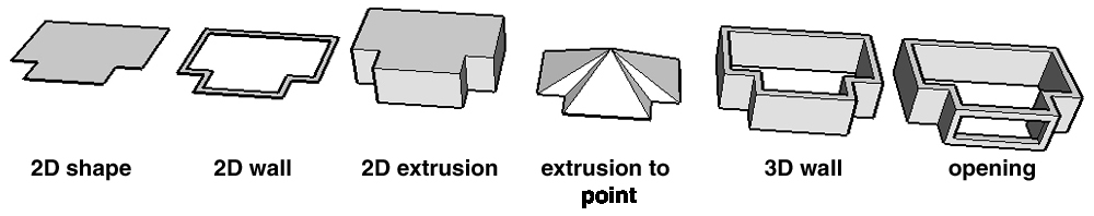
The types of objects that can be generated.
The Insert option in the tool options palette for the Draw tools determines whether an existing object will be modified. When it is on and the drawing occurs on a face of an existing object, the drawn shape is inserted into the original object. When this option is off, a new object is created. If the drawing does not start on a face of an existing object, the Insert option is ignored and a new object is created. The cursor shows if an insertion will occur or not. It displays a plus sign ( ![]() ) when the insert option is on and the cursor is positioned on a face.
) when the insert option is on and the cursor is positioned on a face.
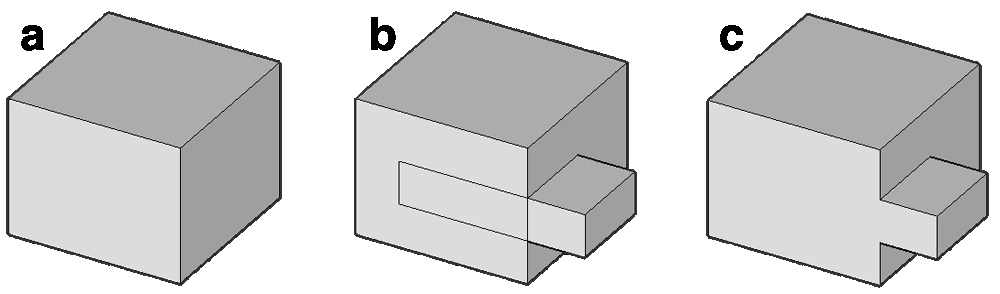
Examples of insertions are shown below:
(a) The original object.
(b) With the 2D type on, a single line is drawn and inserted.
(c) With 2D on again, a rectangle is drawn and inserted.
(d) With 3D Extrusion on, the same rectangle is drawn first and then a height is defined with an additional mouse click.
(e) Everything is as in (d) except that the height is now set in a negative direction and the extruded volume is subtracted rather than being added to the original object.
(f) With 3D Extrusion on, a rectangle that extends beyond the bounds of the face is drawn and then a negative height is defined. In this example a rectangle can either be drawn on the top face or the front face, both producing the same result.
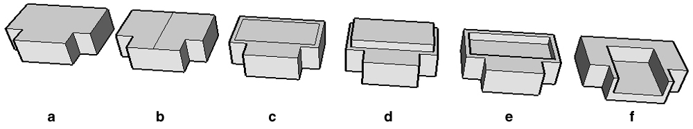
Examples of insertions.
As illustrated above, the insertion works in conjunction with the object type. That is, inserting with the 2D type on inserts the new shape into the original face, while inserting with the 3D Extrusion type adds or removes material from the original object. The 3D Extrusion, 3D Extrusion to Point and 3D Wall types all add or remove material from an object. For these types their tool options palettes contain a few options that control if material is added or removed, and whether edges and material assignments are kept.
Insert menu: This is active when Insert is on.
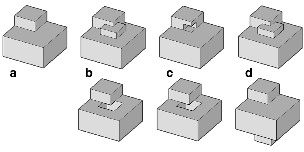
How insertions are affected by insertion options: (a) Original object.
Volume is drawn with height (top:) up and (bottom:) down.
Using (b) Cut and Fill, (c) Cut, and (d) Fill.
The Keep Edges option:(a) Original object. Option is (b) on and (c) off
Cut and Fill: If the 3D object is drawn upward (away from) the base face, material is added to the object. If the object is drawn downward (into) the base face, material is removed (cut out).
Cut: This method always removes (cuts) material from the object regardless of the direction from the base face.
Fill: This method always adds material to the object regardless of the direction from the base face.
Keep Edges: This option affects what happens to edges of faces that are co-planar with the inserted geometry. By default these edges are removed. This option can be enabled to keep these edges as they may be useful for further modeling steps.
Keep Material: This option determines the material that is applied to the newly created faces. When this option is on, the material of the face being inserted into is used. When this option is off, the active material is used. This option is on by default.
Height: This field may perform two different tasks. When Dynamic is off, the height of a 3D object is preset and takes the value in this field. When Dynamic is on and the height is entered interactively, after it is entered its value is displayed in this field. When preset height is used, a value for the height can also be picked from the pop-up menu next to Height.
Source Object: These parameter fields appear in the tool options palette as soon as the drawing of an object has been completed. They represent the dimensions of the base shape and they can be used to change them while the object is in edit mode.
Options of the Polygon tool
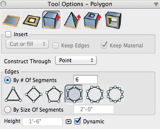
The Polygon Tool Options palette.
At the top of the Polygon tool options palette are the options common to all the drawing tools. They are followed by more options unique to polygons.
The Polygon Drawing popup menu contains three items that affect how the polygon is drawn: With Center & Radius (default) the first point defines the center and the second the size of its radius. With Diameter both points are on the polygon’s circumference. X, Y. Dimensions is as Diameter except that the X,Y of the second point are interpreted independently. The Construct Though popup menu contains two items: Point places a point at the second click. Segment places a segment.
The Edges group offers two methods for setting the resolution of a polygon: By # and By Size Of Segments. For By #, you can type the number of segments in its field or pick one of the icons. For By Size you type the desired segment size in its field. Note that the ultimate size of the segments will depend on the size of the polygon.
Height has the option to be applied in a Dynamic fashion, where the height is specified interactively in the modeling window. The Height may also be a constant value when such value is entered into the Height box, and Dynamic is unchecked.
Appending to open wires
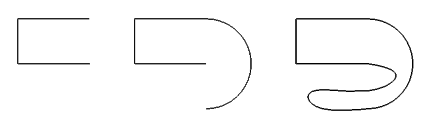
(a) A vector line is first drawn. (b) Starting at an end point
of the vector line, an arc is drawn, which connects. (c) Again,
starting at an end point of the previous shape a spline is drawn,
which also ends at the other end point of the previous shape.
At the end, all three lines have been connected to one closed shape
When using the 2D method with any of the continuous drawing tools the insert option can be used to append new shapes to existing open wire objects. When the cursor is positioned at the end of an existing open wire object, the cursor includes a plus sign to indicate that the new shape will be appended to the existing shape. See illustration.
Modifying results
When a drawing operation results in a new object (i.e. no insertion occurred), the result object is shown in orange and graphic controls become visible. This indicates that its parameters can be modified. The on screen controls can be graphically edited at this point to change the shape. Many settings in the tool options can also be changed at this time. Clicking away from the controls will start the drawing for the next object and the recently drawn object will no longer appear in orange and the controls will disappear.