 Mesh
Mesh
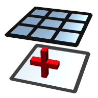
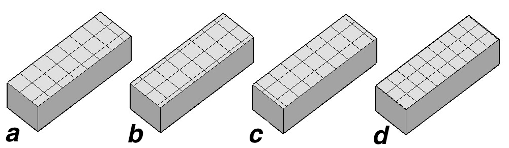
(a) Original object,
(b) whole object meshed, and
(c) selected faces meshed.
The Mesh tool options palette.
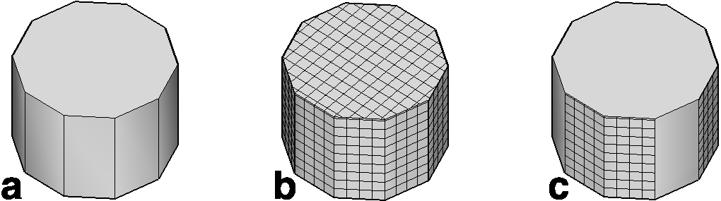
(a) Original object,(b) default mesh direction,
and (c) mesh after rotation.
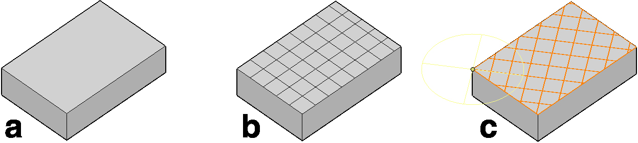
(a) Normal Alignment, (b) Center On Line, (c)
Center Between Lines, and (d) Fit Increment.
This tool is used to generate a rectangular mesh to either all or selected faces of an object. To apply it, with the tool active, click on an object, which meshes the whole object. Or, to mesh a face individually, apply the operation as above, but use the tab key to select the face you wish to mesh. See examples of both. The prepick method can also be used to mesh more than one face in one step.
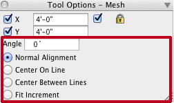
The size of the mesh is determined by X and Y parameters in the Mesh Tool Options palette. When the lock option is on they are constrained to the same value.
|
When a complete object is meshed, the direction of the mesh is determined by the program. When applied to a single face, after the initial generation of a mesh, the user has the opportunity to move it and to rotate its direction through a circular control that appears as soon as the mesh is generated. The orientation of the mesh can also be set by entering a value in the Angle field. See illustration. Four options in the tool palette affect the positioning of the mesh. Normal Alignment does no adjustment. Center On Line places a mesh line at the center of a face and then arranges the mesh on both sides. Center Between Lines places the center of a tile at the center of a face. Fit Increment adjusts the given tile sizes so that only complete tiles are generated. |
New in v. 3.0 |
